


Desertcart purchases this item on your behalf and handles shipping, customs, and support to Greece.
โ๏ธ Take control of your brushless motors like a pro โ power, precision, and protection in one sleek controller!
The RioRand 350W 6-60V 3-Phase PWM DC Brushless Motor Speed Controller with Hall Sensor is engineered for 120ยฐ electric angle 3-phase BLDC motors, delivering up to 350W peak power and 20A peak current. It offers versatile speed control via potentiometer, analog input, or PWM signals, plus forward/reverse and brake functions. Designed with user-friendly terminal blocks, built-in overcurrent protection, and a heat sink for stable thermal performance, itโs ideal for DIY robotics, electric tools, and industrial automation requiring precise, reliable motor speed regulation.
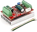


| ASIN | B087M2378D |
| Brand | RioRand |
| Brand Name | RioRand |
| Customer Reviews | 4.1 out of 5 stars 215 Reviews |
| Horsepower | 350 Watts |
| Included Components | controller |
| Item Weight | 77 Grams |
| Manufacturer | RioRand |
| Material | Copper |
| Material Type | Copper |
| Model | KJL-01-with-Hall-Sensor |
| Model Name | KJL-01-with-Hall-Sensor |
| Model name | KJL-01-with-Hall-Sensor |
| Number of Items | 1 |
| Part Number | KJL-01 |
| Speed | 6 |
| Voltage | 60 Volts |
| Wattage | 400 watts |
C**G
Well built and easy to use.
These motor controllers work well with big DC motors. You can only run one motor off of each one. You do not have to use all of the pins to control the device with arduino or esp32. R_ls and L_ls can be left with no connection. The enable pins can simply have 5v applied directly or can be switched. The only thing that might be of concern is the heat sink is on the other side of the board from the mosfets. I really don't think that they will dissipate any heat the unit heats up under high load.
J**G
Good value
Used on a hoverboard motor and works well.
J**N
Good controller, with a few gotchas
This controller ran great out of the box for me. It drove a 24V 6A motor with ease. No heat issues and high torque. If you're going to use the PWM mode to control the speed, make sure you remove the jumper next to the speed pot on the controller board. If it weren't for a couple of gotchas, I would have given it 5 stars. Gotchas: The controllers power down in PWM mode after a few seconds connected to +5V power, and then they don't re-enable. It seems that the PWM channel is very sensitive to noise and so something causes the controller to shut down. I could "wake" it back up by wiggling the wire connected to the +5V power to the controller. If you are using an Arduino, instead of connecting the 5V terminals on the controller to a +5V power source, connect it to one of the Arduino's digital pins instead. These pins are at TTL logic levels (+5V) and they provide enough power to supply the logic on the controller. You can then toggle the pin on and off to enable and disable the controller. When the motor is stopped or you want to stop the motor, set the pin to LOW so it clears the controller of any internal shutdown mechanism. When the motor needs to move, set the pin to HIGH and the controller logic will power up and resume. The brake isn't really a brake. It just cuts the power to the motor and has no holding torque. There's no power that goes to stop any momentum from the motor, so the motor stops itself through friction. This is way cheaper than a lot of controllers out there and I think it's a great value for prototyping mechanical setups without having to spend much money!
A**O
Simple
Really simple and good to use
J**N
PWM pin solved plus pulse for RPM!!
I have the Hall Sensor version. Spent a lot of time finding the correct phase wiring order. But hardest part was getting the PWM to work. First: The jumper is needed, mine was just solder pads so I soldered pins and put jumper. Refer to the picture linked to this product. Second: The tiny 5 pin pads on the same side as the jumper, the Vcc and Gnd are same as the screw terminal (for pot). You will need to solder a pin to the one marked "P". I used the screw terminals for Vcc and Gnd (caution, they are 5v). PWM connection to the "P" pin and you are good to go. I am using SEEED nRF52840 and it is 3.3v but it has a 5v pin, I power it off the motor driver and the PWM works great with only 3.3v output from digital pin. I'm running at 20k PWM freq. Only 4 stars as no documentation and a lot of trial and error to run down the wiring. Ok, I changed to 5 stars as I found that the middle pin on the side with my last picture with clip is "PULSE" output. I used interrupt to count the pulses and then divided by 12 to get one revolution.
Trustpilot
1 week ago
2 months ago