


⚡ Unlock 16 channels of seamless PWM magic with just 2 pins!
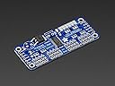
The Adafruit 16-Channel 12-bit PWM/Servo Driver (PCA9685) is a compact, I²C-controlled board that enables precise PWM output management without continuous microcontroller intervention. Featuring a built-in clock, reverse polarity protection, and the ability to chain up to 62 units for nearly 1,000 outputs, it’s ideal for advanced robotics, LED lighting, and servo control projects.
| Best Sellers Rank | #672,696 in Industrial & Scientific ( See Top 100 in Industrial & Scientific ) #320 in Motor Drives |
| Customer Reviews | 4.8 out of 5 stars 46 Reviews |
G**T
Five Stars
My favorite PWM driver, so easy to use with Adafruits sweet support libraries.
M**.
Four Stars
Worked as expected!
H**P
It works but holes aren't standard M3 size!
UPDATE [NOV 11/2014] WARNING: THE FOLLOWING EXPLANATION CAN MAKE YOU FEEL CHICKEN SKIN!! I've drilled the holes to expand the diameter 1 to 1.5 mm!! Just put the board through the light, you'll see a clearance around the holes! This is like a space to prevent screws from damaging the PCB layers. I've drilled the holes carefully and now I can use M3 1/4 inch screws to hold the device! I tested the whole PWM output pins and fortunately everything gone well! Why don't you Adafruit guys didn't prevent this situation to avoid us, your customers from doing this?? Or just tell what size the holes is (M2.5, M2 ??) UPDATE [NOV 10/2014] After testing my project and preparing for assembly, I get frustrated when I used some spacers to mount on the controller but they didn't fixed the holes!! I'm now looking for something to replace the spacers to hold it steady! Went to the adafruit's web page and found nothing about the size of the holes! This servo controller does its job! I used my pcDuino v2 to post the commands through the TWI (I2C) directly to the registers of the PCA9685. I've activated the AI bit in REG_MODE1 to allow continuous writing on the ON/OFF L/H LED/SERVO registers, so I can send the four bytes for a single channel in one I2C transaction! I also configured the PRE-SCALE register to set the frequency I needed. This is done by first putting it in SLEEP MODE. Once configured, I just needed to send the timing values to allow the unit to mux the PWM independent values to every single channel and adjust the duty cycles. Unfortunately, pcDuino v2 just work in between the standard and fast mode on the I2C bus (200 kHz), but it works just fine. It effectively frees the MCU from holding the PWM signal on your servos so you can use those extra CPU cycles on whatever processing you need. There is just one complain regarding its linearity. I used a linear regression to map step values (0 - 4095) to time values (more appropriate for servo timing). I noticed some lag on the OFF time for the pulse while increasing the duty cycle. I needed to make some adjustments by hand to fix this behavior. Anyway, it made my day and now have a very nice servo controller!
Trustpilot
3 days ago
1 month ago