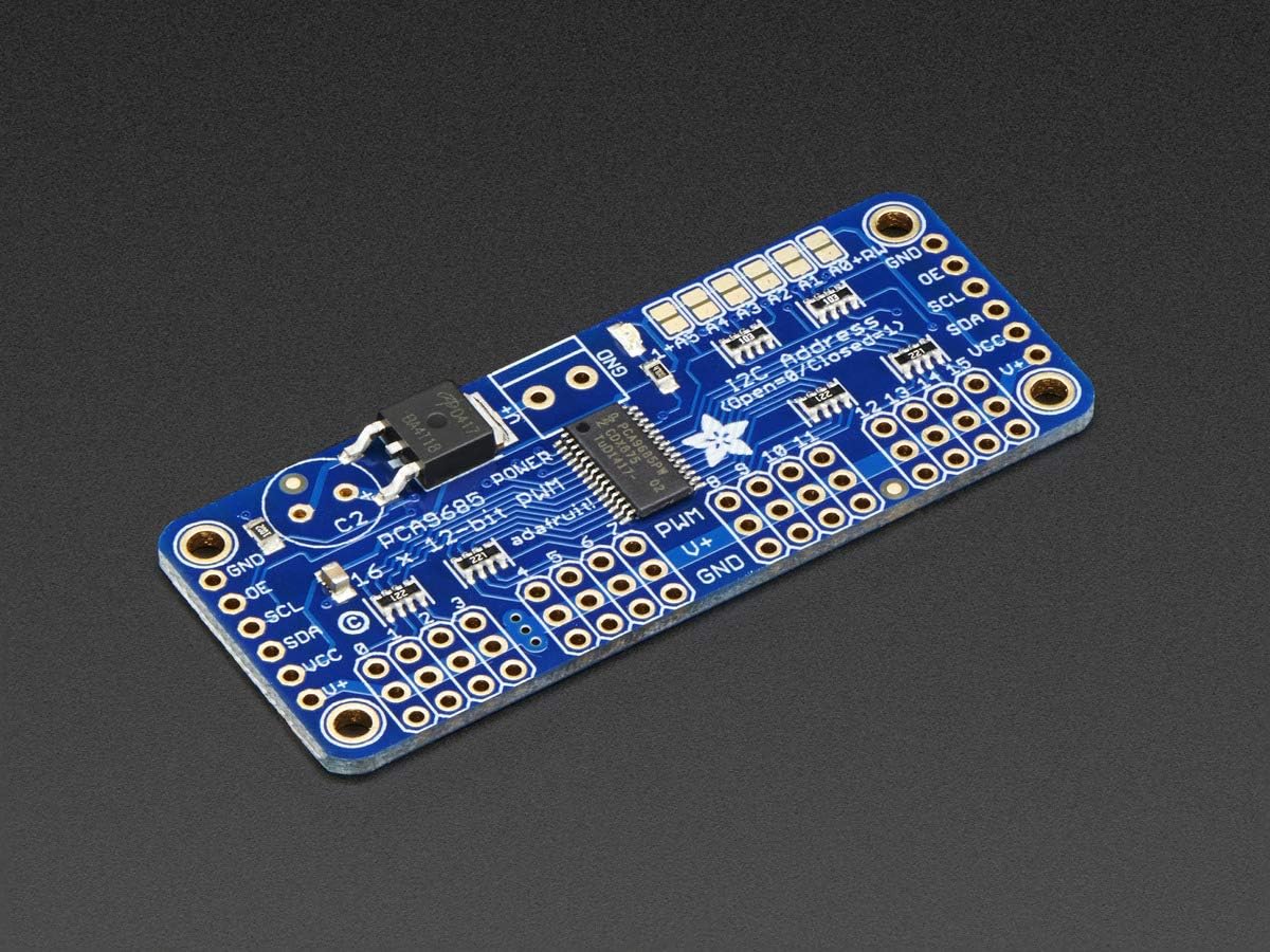
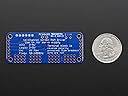
This 16 channel PWM generator board by Adafruit, is particularly useful if you have an application which requires multiple PWM signals which doesn't burden the processor. Once configured, the on-board PCA9685 controller chip does the job of outputting each PWM signal. To change the duty-cycle of a particular channel, perhaps to operate the position of a servo, you only need to write to the appropriate 12bit registers in the PCA9685.The CPU you use to communicate with each board (maximum 62) can be anything which uses the I2C protocol e.g. Arduino, Raspberry PI, Microchip PIC's etc. The base address of each board is set to 0x80 (eight-zero Hexadecimal) so if your application uses more than one of these boards, then you need to select a unique address for each board. Gold-plated jumper contacts are provided to allow this - you solder across adjacent contacts which form the address selector. Shorting contacts A0 only, would select the base address 0x82 for a second board and shorting contacts A1 only, would select the base address 0x84 for a third board etc.Whichever processor you use to control the Adafruit 16 channel PWM board, remember to include a resistor on both the I2C's SCL (clock) and SDA (data) lines pulled-up to the voltage used, which could be 3.3V or 5V depending on the processor. I've used 2k2 resistors for use with four daisy-chained boards. Controllers such as the Arduino Mega have dedicated I2C (SDA and SCA) pins so pull-up resistors are not required in this case. This PWM board is specified to have 5V tolerant inputs so will operate with 3.3V powered CPU's.My application uses four of these boards to control the brightness of sixty four 230V bulbs arranged in a 8x8 matrix. The bulbs are controlled by IGBT devices which are optically-isolated from the Adafruit PWM boards for complete safety. The output from a single PWM channel is capable of driving an LED (or opto-coupler) directly, but it's good practice to buffer the outputs if using multiple LED's to increase the reliability of each Adafruit board.No information was supplied with the Adafruit 16 channel PWM board as this is readily available from the Adafruit website. Drivers and data sheets for the PCA9685 chip are also available by searching the web !Nice product which works really well .... recommended.